Your CNC machine tool partner for precision and performance
Our customers come first. We work hand-in-hand with manufacturers to understand their machine tooling, delivering exceptional service, support, and tailored solutions that drive innovation, enhance efficiency, and secure a competitive edge.
Our purpose: future-ready manufacturing partner
We redefine industry standards to keep you competitive, efficient, and ahead in the ever-evolving manufacturing world.
Reliable, honest service backed by experience
With over 40 years of expertise, we provide dedicated and trustworthy service, ensuring precision, reliability, and consistency in every CNC solution.
Innovative CNC optimisation solutions
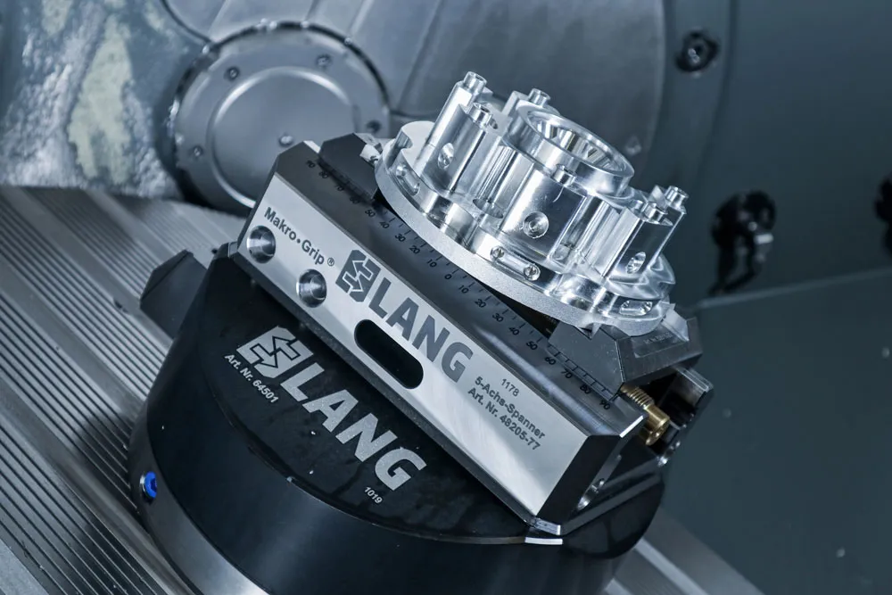
Driven by innovation, our advanced technology and custom workholding systems maximise machine performance, increase productivity, and improve long-term operational efficiency.
Commitment to sustainable manufacturing
We prioritise environmental responsibility with sustainable CNC solutions that promote longevity, reduce waste, and help you maximise your return on investment - offering a future-focused approach to manufacturing.
Unmatched customer care and support
Our commitment extends beyond sales. We’re dedicated to building lasting partnerships and providing expert after-sales support, giving you peace of mind on your purchase.


Let's discuss your CNC machine tool needs

Coming soon
Simple online ordering for a wide range of CNC machine tool products
Our range of CNC machine tool products will be available for convenient online ordering.


